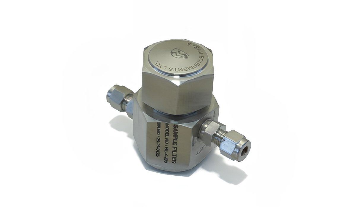
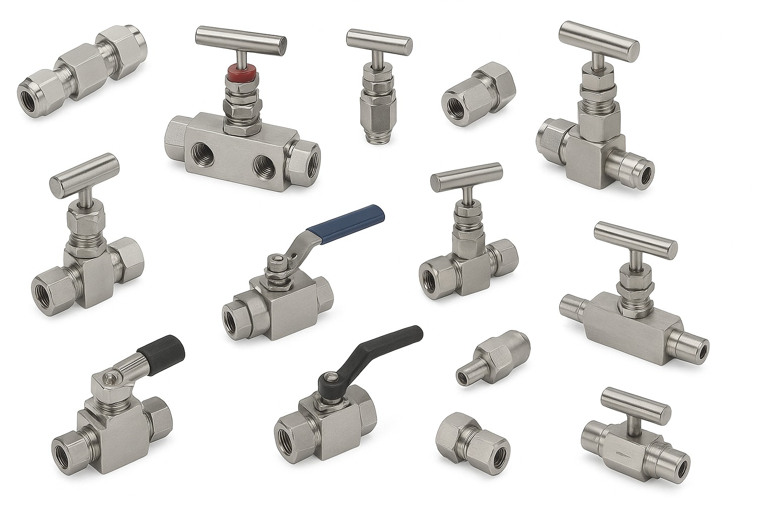
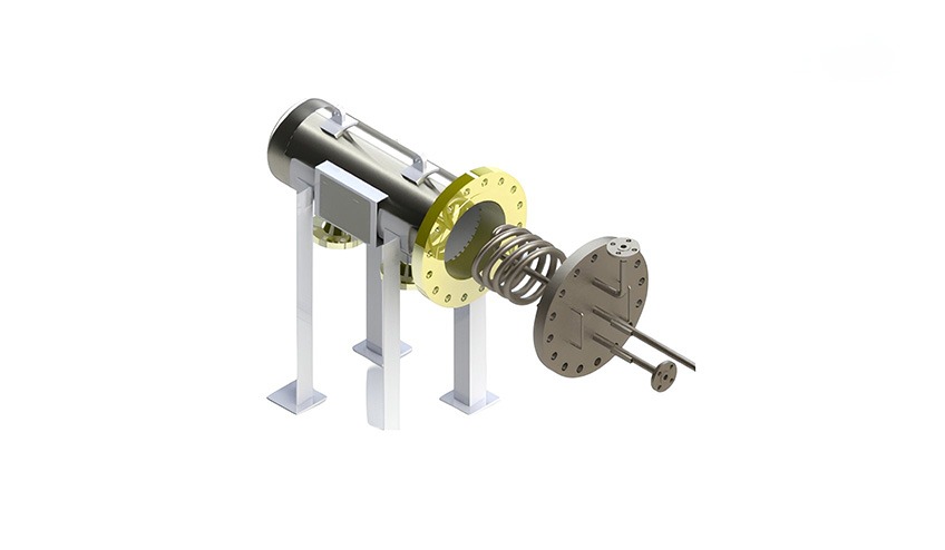
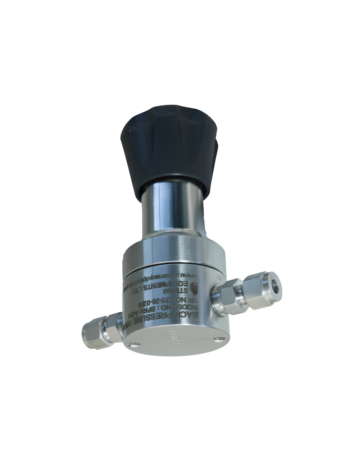
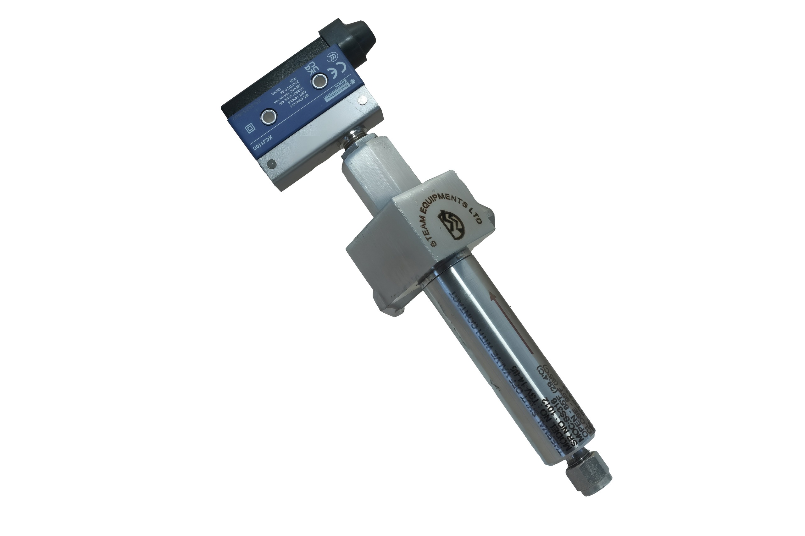
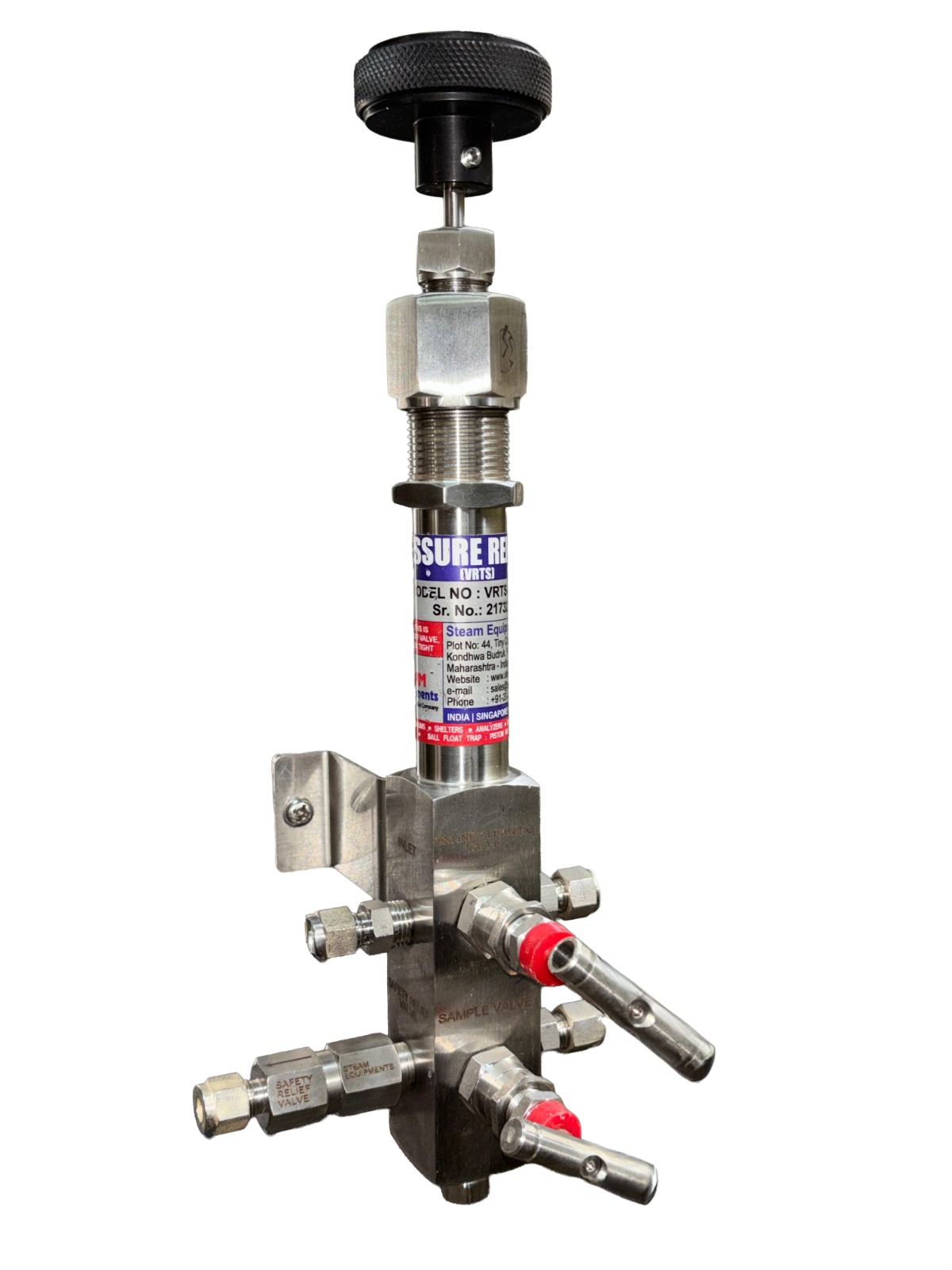
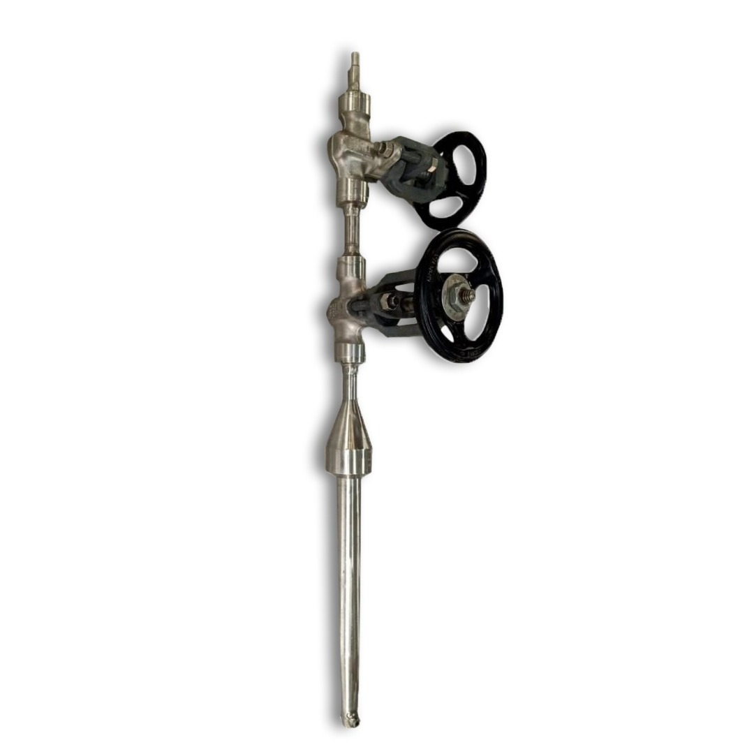
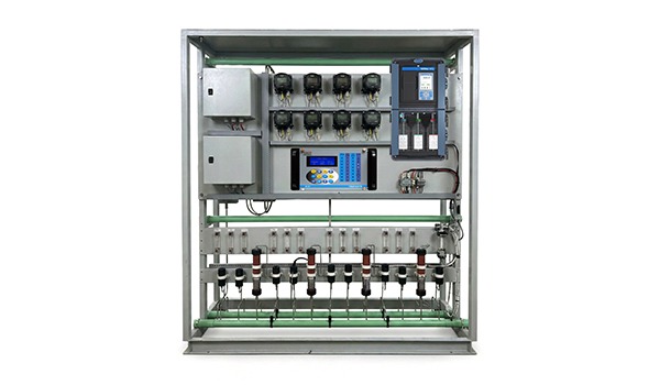
Description
This valve is installed in the downstream of sampling systems/heat exchanger. The valve responds only to temperature. Under normal operation, the valve is fully open. If the sample temperature increases within the operating temperature (120ºF), The thermal actuator modulates the valve to close the inlet orifice. The valve automatically opens as the thermal actuator cools. The heart of this valve is a solid to liquid phase change thermal actuator. The actuator contains Thermoloid® compound which changes phase from solid to a liquid as the temperature increases. As phase change occurs, the volume of Thermoloid® material changes significantly with the liquid volume greater than the solid volume. Since Thermoloid® is essentially incompressible under normal operating loads & it is sealed into a rigid actuator housing, only piston can move and extend as the volume increases. This motion is used to open or close the valve.
Features
• Automatic: No reset or Operator involvement required.
• No outside Power Source required.
• Rugged, Compact Design, Easy Installation, Fast response.
• Reliable Shut-off : Ram-type plug design provides tight seal upon shutoff.
• Operating temperatures unaffected by pressure.
• Wide Choice of Set points.
• Corrosion Resistant: Materials Stainless steel and Teflon to reduce contamination of Sample stream.
• Operates in any orientation.
• Maintenance free.
Benefits
• Purely Mechanical process.
• Reliable shut-off: Ram-type plug design provides tight seal upon shut off.
• No malfunctioning possibility.
• No operator attention required.
• Keeps costly elements of systems like Analysers safe.
• Maintenance free.
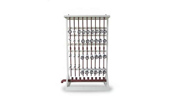
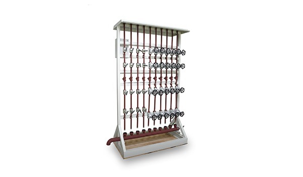
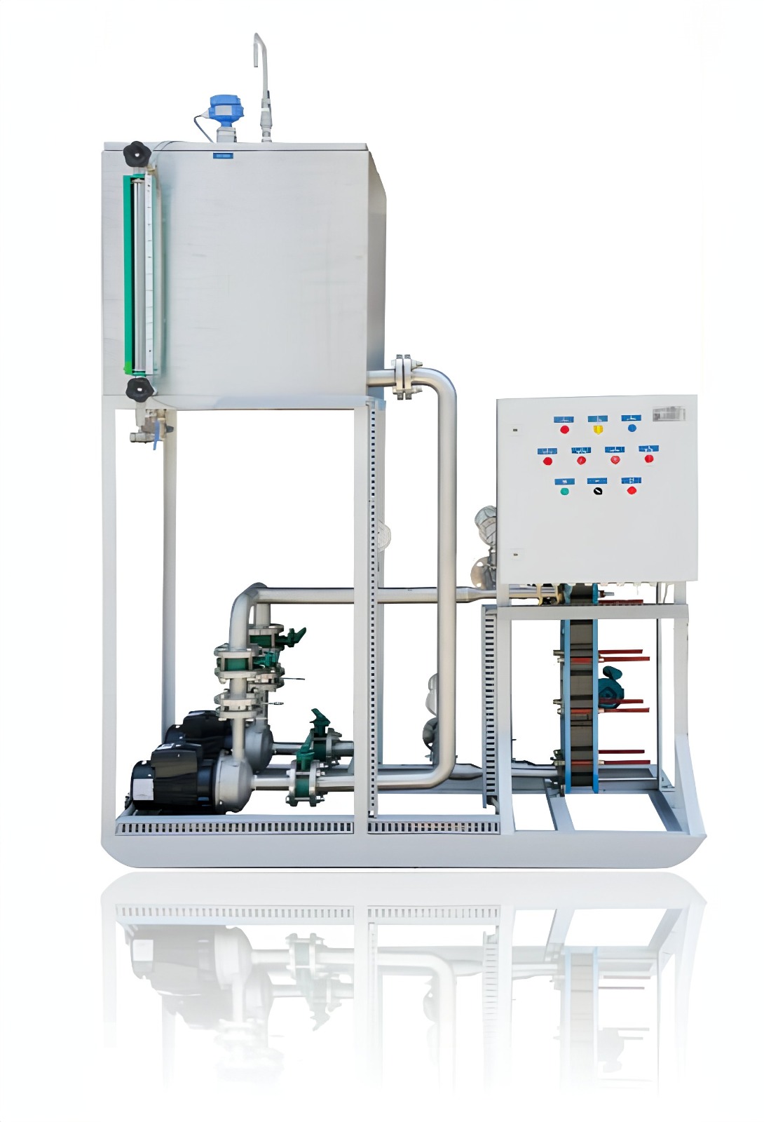
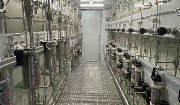
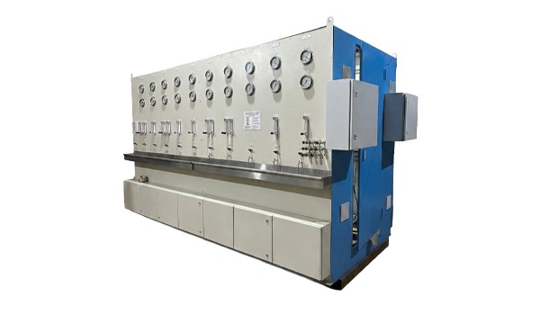
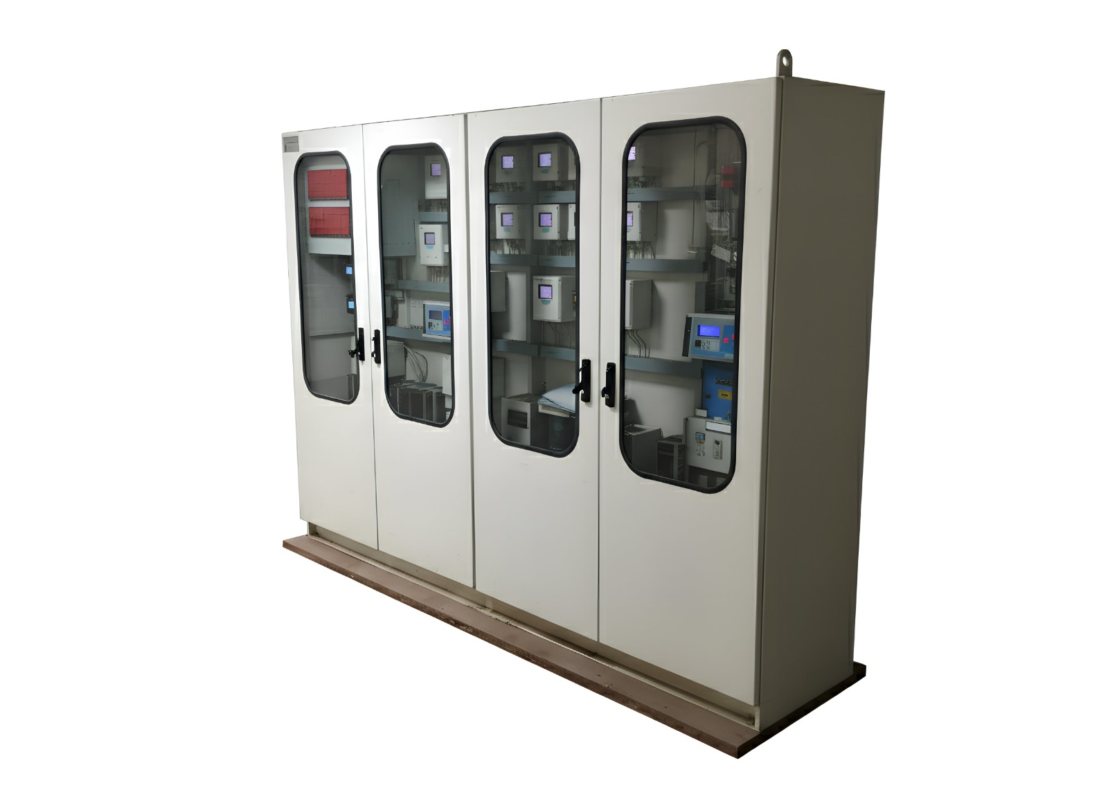
Applications
TSV is used in Steam & Water Analysis Systems, Instrumentation systems, etc.
• Steam & Water Analysis Systems.
• Instrumentation systems.
• Steam and Water Sampling Systems.
• Automatic Thermostatic Bypass.
• Thermostatic Flow Control.
• High or low Temperature Relief Valve.
• High Temperature Safety Shut-off.
• Thermostatic Drain Valve.
• Thermostatic Cooling Water Control.
• Thermostatic Condensate Drain.
• Heat Exchangers.
Specifications:
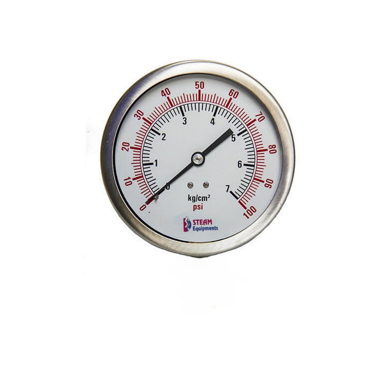
• Maximum Pressure Rating = 3000 psig
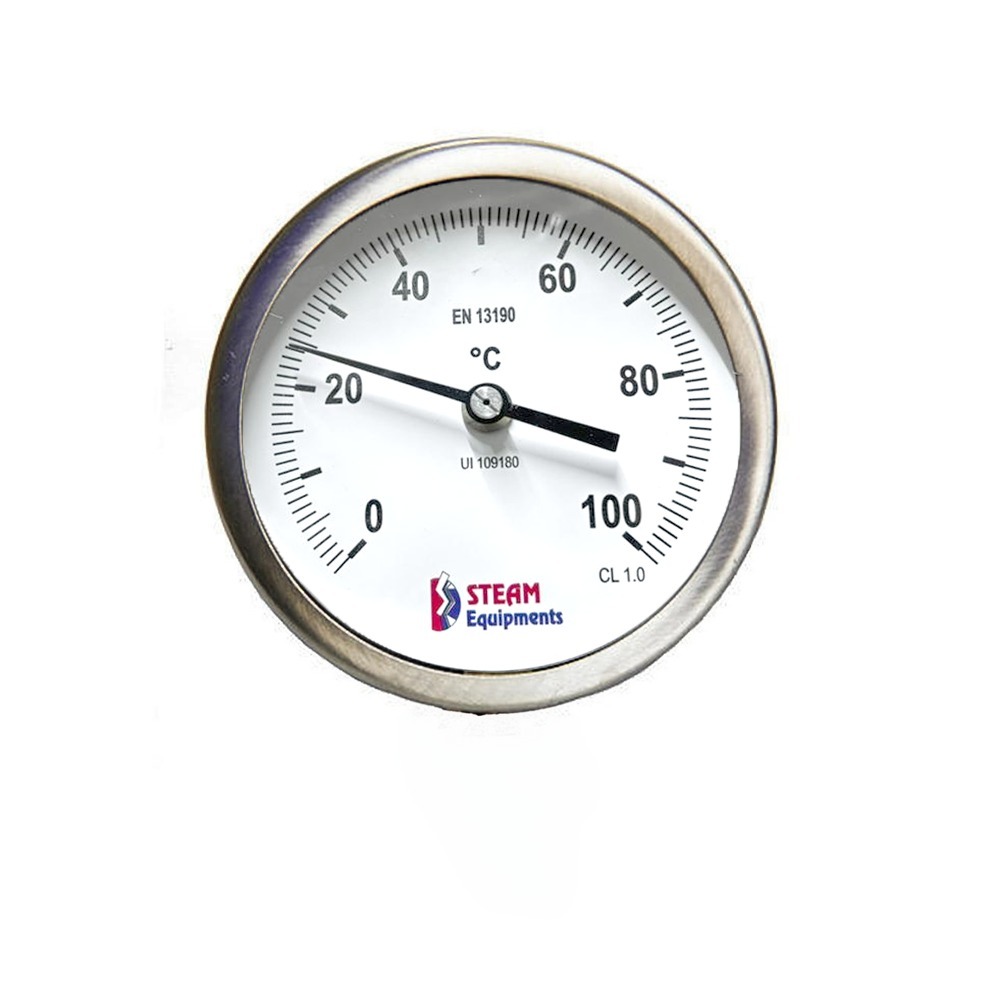
• Maximum Temperature Rating = 120 °C
• Valve Open Temperature (std) = 43 °C
• Valve Close Temperature (std) = 48 °C
• Sample connection = ½” NPT (F)
• Non standard ranges and connections available