Description


Steam Equipments in collaboration with Ross Boiler, Ross Boilers manufacture and supply Reverse Osmosis Plants. Typical applications of RO plants are in the food processing and pharmaceutical industries.

Description


Steam Equipments in collaboration with Rose Boiler, Ross Boilers manufacture high-quality Hot Air Generators. Our hot air generators come with robust construction and easy operation. Our units are available from capacities of 20,000 kcal/hr to 30, 00,000 kcal/hr. Our hot air generators are manufactured using the latest technology, under the supervision of experienced professionals.

Description


Steam Equipments in collaboration with Rose Boiler, Ross is one of the top Hot water generator manufacturers. A wide variety of hot water generators in standard designs are available for various applications. Our hot water generators are dependable and stand out for their long life and trouble-free operation. These units are Rugged with long service life.

Description


Steam Equipments in collaboration with Ross Boiler, Ross Boilers is one of the top Steam Boiler Manufacturers in the world. We manufacture a wide variety of industrial steam boilers with different firing options like oil, gas, solid and electrical.

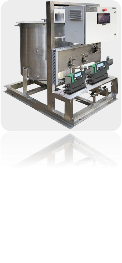
Chemical Dosing System
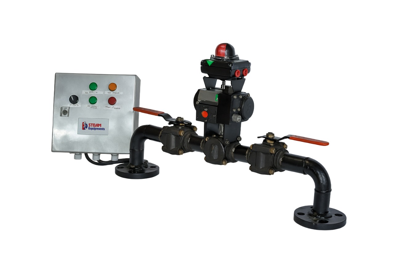
Image 1

Description


A Dosing System is a water treatment solution that automatically maintains the correct pH and chlorine levels in water systems, such as swimming pools, cooling towers, wastewater treatment plants, and drinking water systems.

Key Components:
  • pH Sensor & Controller: Measures and adjusts the pH level by adding acid (to lower pH) or alkali (to increase pH).
  • Chlorine (Hypochlorite) Sensor & Controller: Monitors chlorine levels and doses sodium hypochlorite accordingly to maintain proper disinfection.
  • Dosing Pumps: Precisely inject chemicals into the water system.
  • Mixing Chamber: Ensures proper dispersion of chemicals.
  • Data Logging & Remote Monitoring (Optional): Some advanced systems allow remote control and real-time monitoring.
Blowdown System
Image 1
Image 2

Description


A blowdown system is a safety and maintenance mechanism used in industrial facilities to release pressure, remove contaminants, or drain fluids from equipment such as boilers, pressure vessels, and pipelines.

It typically consists of valves and piping that allow controlled discharge of steam, gas, or liquid to prevent overpressure, maintain water quality, or prepare equipment for inspection and repair. Blowdown systems are essential for ensuring operational safety, efficiency, and compliance with environmental standards

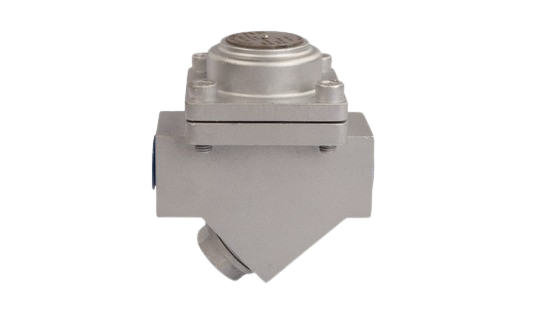
Thermostatic Air Vent Trap – Slavt76-vh
Image 1

Description


  • Corrosion Resistant Stainless-Steel Construction with Inbuilt Filter
  • Thermostatic Element Designed for Wide Pressure Range
  • Testing 100% on Steam
SIZE(NB) PMA TMA END CONNECTION
15, 20, 25, 40, 50, 65, 80, 100, 125, 150, 200 19.6 bar(g)
5.5 bar(g)
51.1 bar(g)
28.8 bar(g)
-29 to 38°C
425°C
-29 to 38°C
425°C
ASA 150
ASA 300
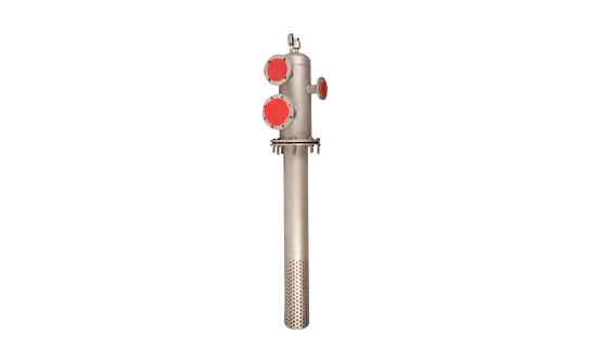
Deaerator Head – Slda 95
Image 1

Description


  • SS Construction to Avoid Corrosion & Hence Longer Life
  • Unique Design for Condensate, Makeup Water & Flash Steam Inlet
  • Ensures Proper Mixing, Better Efficiency & Uniform Temperature
  • Discharge Unit is SS304 Ensuring No Corrosion
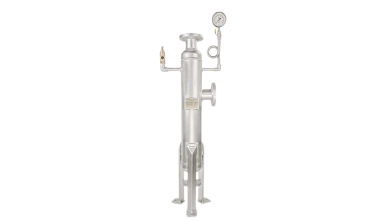
Flash Vessel – Slfv 96
Image 1

Description


  • Maximum Flash Steam Recovery
  • Zero Maintenance Product
  • Customized to Customer Requirements
  • Available in IBR as Special
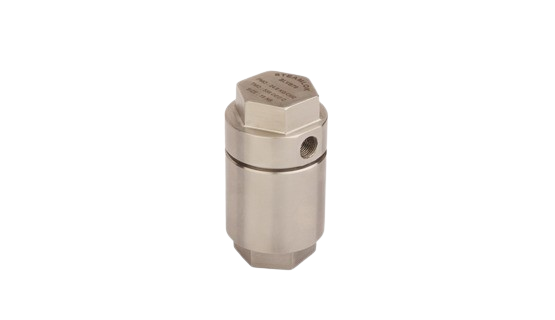
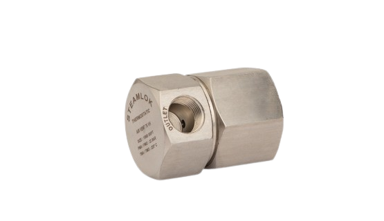
Vaccum Breaker - Slvb 76
Image 1

Description


  • Stainless Steel Construction
  • Robust Design
  • Testing 100% on Steam
SIZE(NB) PMA TMA END CONNECTION
15, 20, 25, 40, 50, 65, 80, 100, 125, 150, 200 19.6 bar(g)
5.5 bar(g)
51.1 bar(g)
28.8 bar(g)
-29 to 38°C
425°C
-29 to 38°C
425°C
ASA 150
ASA 300
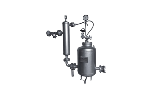
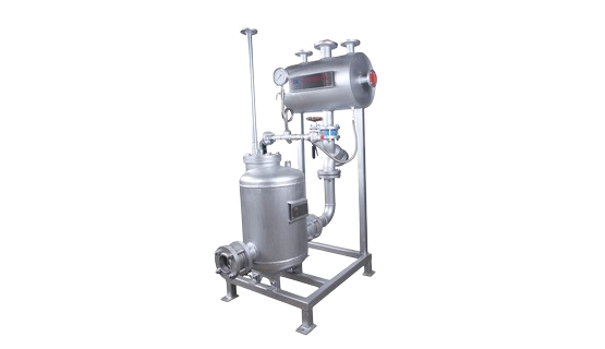
Condensate Recovery Pumping Trap – Slcrpt 75
Image 1

Description


  • Inbuilt View Glass for Online Monitoring
  • Two Different Assembly for Pump & Float Trap Mechanism
  • Easy Maintenance of both Pump & Float Trap Individually
  • Discharge Capacity is 2800 kg/hr
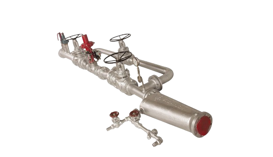
Pressure Reducing Station (prs / Prdsh) - Slprs 97
Image 1

Description


  • Complete Solution for Pressure Reduction, De-Superheating & Temperature Control
  • Pneumatic Actuated Control Valve
  • Piston Valve as Isolation Valves
  • IBR Approvals
Condensate Recovery Pump – Slcrp 75
Image 1

Description


  • Body MOC Carbon Steel
  • Internals in SS ensure no corrosion & longer life
  • Viewing Glass for Monitoring
  • Unique Spring Design for Longer Life
  • Overall Very Compact Design
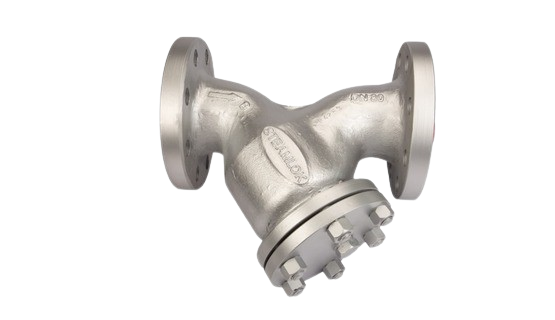
Strainers - Slstr 15/25
Image 1

Description


  • Bolted Strainer Cap above 40 NB Size for ease for Maintenance
  • Drain Plug as an Optional Feature for easy Upkeep of Strainer
SIZE(NB) MOC END CONNECTION
25, 40, 50, 65, 80, 100, 125, 150, 200 WCB Screwed, Socket Weld
Cast Iron ASA 150/ ASA 300
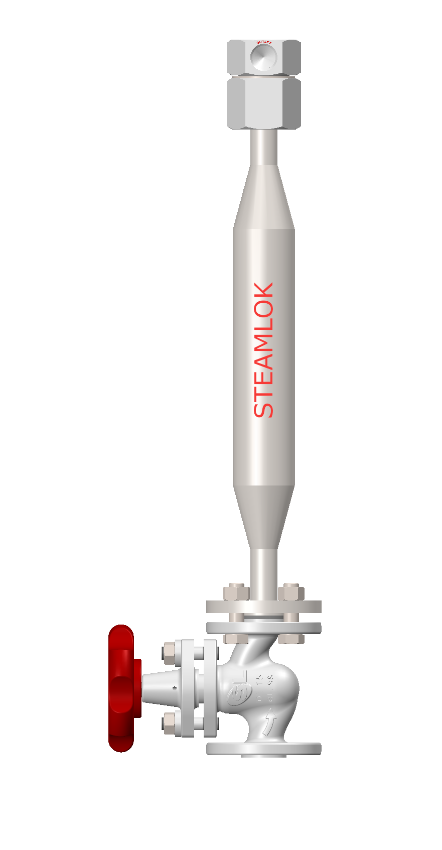
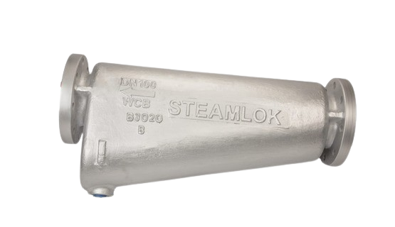
Moisture Separators - Slsep 25
Image 1

Description


  • Baffle Type Construction for Enhanced Condensate Removal Efficiency
  • Suitable for Both Steam & Compressed Air
SIZE(NB) PMA TMA END CONNECTION
25, 40, 50, 65, 80, 100, 125, 150, 200 19.6 bar(g) 5.5 bar(g) 51.1 bar(g) 28.8 bar(g) -29 to 38°C 425°C -29 to 38°C 425°C/td> ASA 150 ASA 300
Thermostatic Air Vent – Slavt 76 Vh
Image 1

Description


  • Corrosion Resistant Stainless Steel Construction with Inbuilt Filter
  • Thermostatic Element Designed for Wide Pressure Range
  • Functional Test - 100% on Steam
SIZE(NB) PMA TMA END CONNECTION
15, 20 49 bar(g) 538°C BSP / BSPT / NPT
Thermostatic Steam Trap – Sltst 35
Image 1

Description


  • Maintainable Strainer Design/li>
  • Thermostatic Element for Wide Pressure Range
  • Functional Test - 100% on Steam
SIZE(NB) MOC PMA TMA END CONNECTION
15, 20 A105 51 bar(g) 425°C Socket Weld, Butt Weld, ASA 600 / 1500
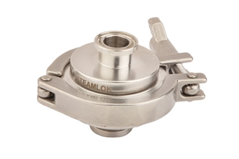
Thermostatic Pharma Trap - Slsst 79
Image 1

Description


  • MOC for All Wetted Parts – SS316L
  • Electro-Polished Internal Finish
  • Self Drainable Body and Cap Design
  • Functional Test - 100% on Steam
SIZE(NB) MOC PMA TMA END CONNECTION
15, 20, 25 SS316L 10 bar(g) 176°C ASME BPE - Tri Clamp, Tube Weld
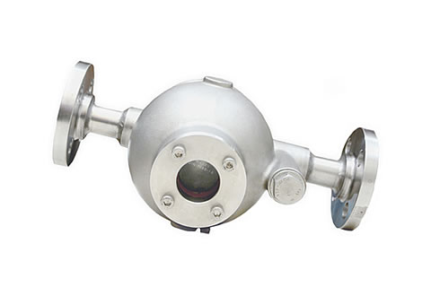
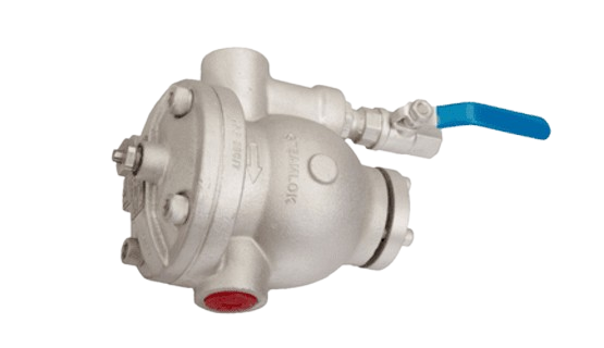
Ball Float Steam Trap – Slft 76 (15nb, 20nb, 25nb)
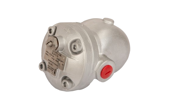
Image 1

Description


  • Maintainable Strainer Design
  • Sight Glass as Standard Feature
  • Functional Test – 100% On Steam
SIZE(NB) MOC PMA TMA END CONNECTION
15, 20, 25 CF8 41 bar(g) 538°C Screwed / Flanged
Eco Ft-70
Image 1

Description


  • Unique Rotating Ball Design for Zero Leak
  • Self-Aligning Steam Lock Release (SLR)
  • Functional Test – 100% On Steam
SIZE(NB) MOC PMA TMA END CONNECTION
15, 20, 25 Cast Iron 13 bar(g) 200°C Screwed / Flanged
Ball Float Trap - Slft 25 (40nb, 50nb)
Image 1

Description


  • Dual Sight Glass for Easy Monitoring
  • Self-Aligning Steam Lock Release (SLR)
  • Functional Test – 100% On Steam
SIZE(NB) MOC PMA TMA END CONNECTION
40,50 Cast Steel (WCB) 51 bar(g) 425°C Screwed / Flanged
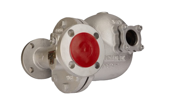
Ball Float Trap - Slft 25 (15nb, 20nb, 25nb)
Image 1

Description


  • Eco Ball Float Steam Trap Design
  • Cast Steel (WCB) Body
  • Self-Aligning Steam Lock Release (SLR)
  • Functional Test – 100% On Steam
SIZE(NB) MOC PMA TMA END CONNECTION
15, 20, 25 Cast Steel (WCB) 51 bar(g) 425°C Screwed / Flanged / Socket Weld
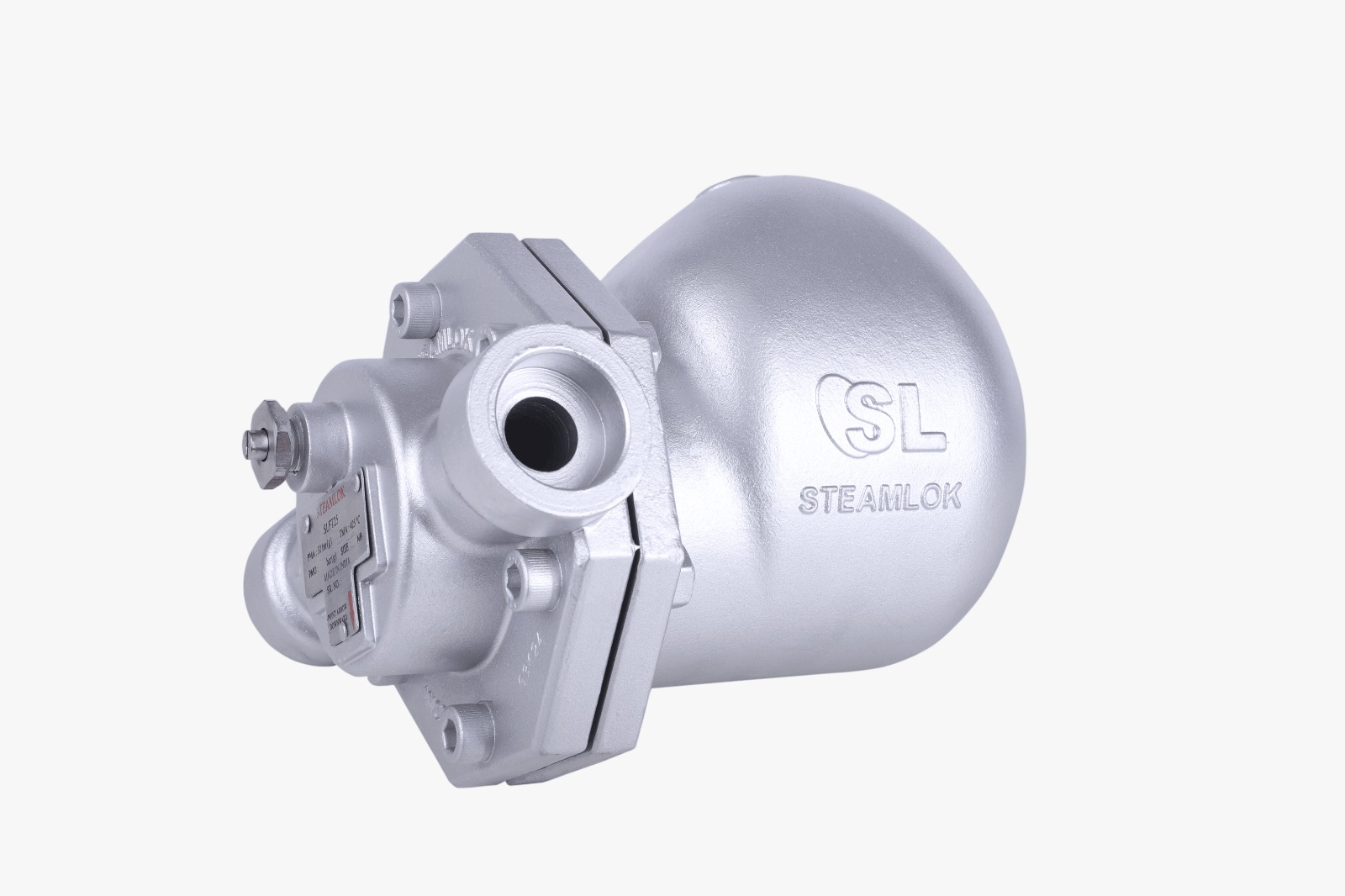
Ball Float Trap – Slft 75 (40nb, 50nb)
Image 1

Description


  • Unique Rotating Ball Design for Zero Leak
  • Self-Aligning Steam Lock Release (SLR)
  • Sight Glass as Standard Feature
  • Functional Test – 100% On Steam
SIZE(NB) MOC PMA TMA END CONNECTION
40, 50 SG Iron 16 bar(g) at 100°C 200°C Screwed / Flanged
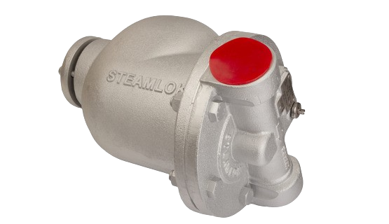
Ball Float Trap – Slft 75 (15nb, 20nb, 25nb)
Image 1

Description


A ball float steam trap is used on steam process lines to remove condensate formed during heating. It operates on the buoyancy principle—using the density difference of steam and water. The float rises and falls with condensate level, continuously discharging it while maintaining process temperature. It handles both moderate and high condensate loads efficiently.

  • SG Iron Construction
  • Maintainable Strainer Design
  • Online Flushing Arrangement
  • On-line Monitoring
  • Self-Aligning SLR Design
  • Functional Test – 100% On Steam
SIZE(NB) MOC PMA TMA END CONNECTION
15, 20, 25 SG Iron 16 bar(g) at 100°C 200°C Screwed BSP / BSPT / NPT / Flanged
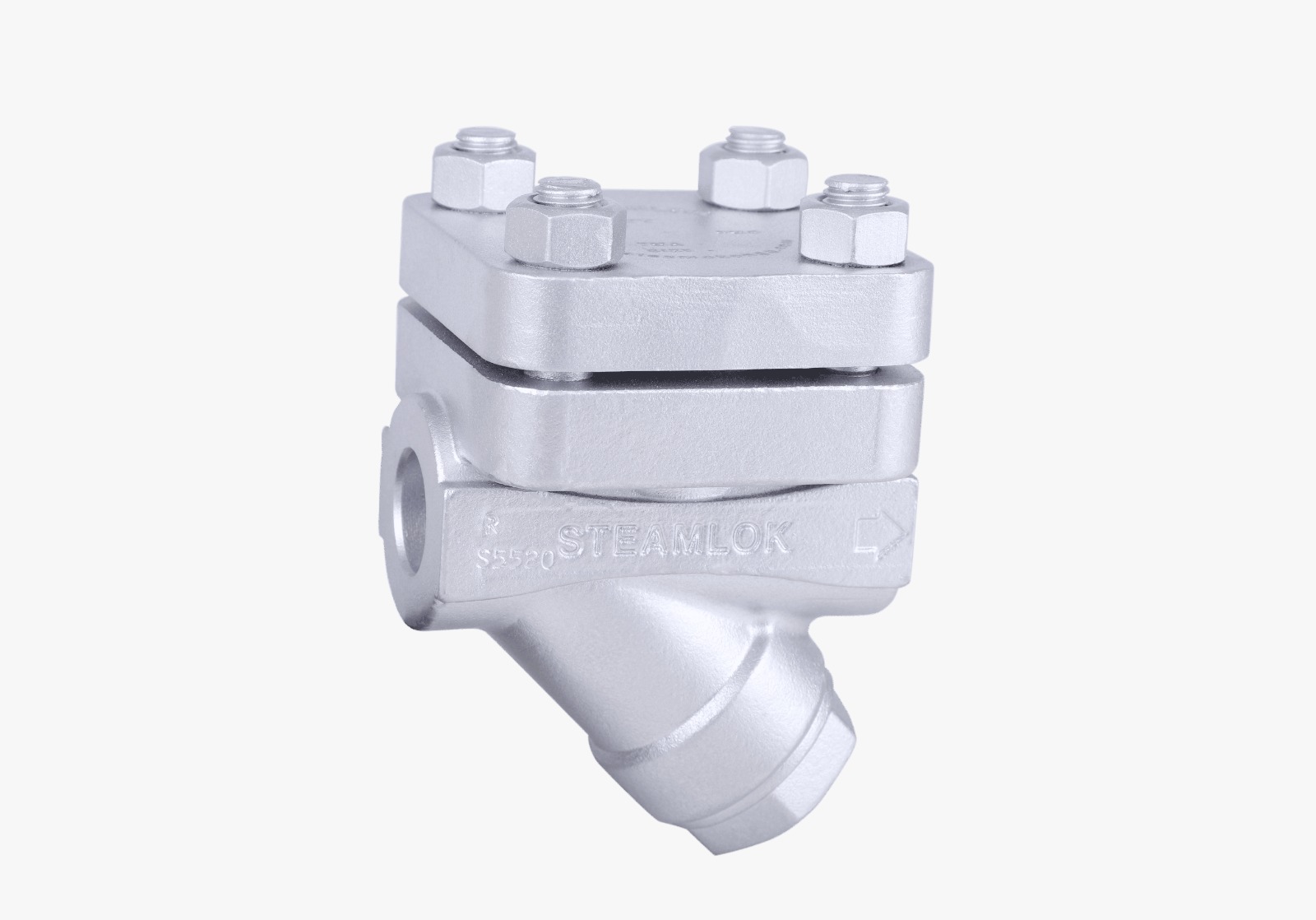
Thermodynamic Steam Trap – Sltt 85
Image 1

Description


  • Maintainable Seat Design
  • Vacuum Heat Treatment (Oxidation Free)
  • Inbuilt Strainer for Easy Maintenance
  • Functional Test - 100% on Steam
SIZE(NB) MOC PMA TMA END CONNECTION
15, 20 A105 65 bar(g) 510°C Socket Weld, Butt Weld, ASA 600 / 1500
Thermodynamic Compact Module – Slcmtt35-c (15nb, 20nb, 25nb)
Image 1

Description


  • Heat Resistant Handwheel
  • Oxidation Free Heat Treatment (Vacuum) for Seat & Disc
  • Unique Sealing Arrangement for Extended Valve Life
  • Functional Test - 100% on Steam
SIZE(NB) MOC PMA TMA END CONNECTION
15, 20, 25 A105 76.6 / 10.5 / 29.3 bar(g) 425°C / 250°C Socket Weld ASA 150 / 300
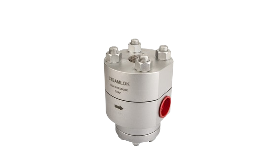
Thermodynamic Trap – Sltt 87/88
Image 1

Description


  • Replaceable Seat & Disc
  • Easy Maintainable Trap
  • Alloy Steel Construction
  • Functional Test - 100% on Steam
SIZE(NB) MOC PMA TMA END CONNECTION
15, 20, 25 SS 304 48.9 bar(g) 538°C Screwed, Socket Weld, ASA 150 / 300 / 600
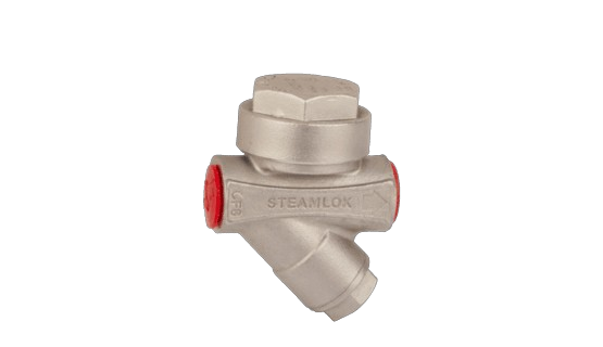
Thermodynamic Trap - Sltt 76
Image 1

Description


  • Uniquely Designed Replaceable Seat & Disc
  • Easy Maintainable Trap
  • Stainless Steel Construction
  • Vacuum Heat Treated Seat & Disc
  • Functional Test - 100% on Steam
SIZE(NB) MOC PMA TMA END CONNECTION
15, 20, 25 SS 304 48.9 bar(g) 538°C Screwed, Socket Weld, ASA 150 / 300 / 600
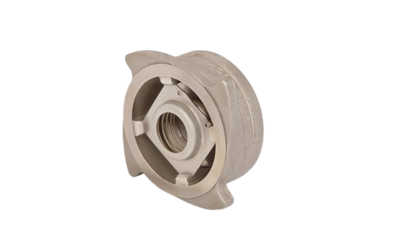
Disc Check Valve - Sldcv 77
Image 1

Description


  • MOC – SS316
  • Compact Design
  • Light Weight
  • Disc Check Valve must be Fitted Between Flanges as per Flow Direction Indicated on Body
SIZE(NB) PMA TMA END CONNECTION
15, 20, 25, 40, 50, 80, 100 49.6 bar(g)
38°C
29.1(g)
425°C Between Two Flanges
ASA 150
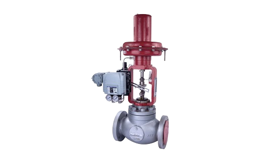
Control Valve (prv/tcv)
Image 1

Description


  • Rangeability 1:40
  • Non Threaded Seat – Maintenance Friendly Avoiding Wear & Tear
  • Reversible Type Seat – Can be used Both Sides Ensuring Higher Life
  • Stuffing Box SS – Ensures Zero Leakage
  • Floating Ring Ensures Perfect Alignment of Plug & Seat
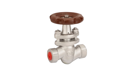
Piston Valves - Slpv25
Image 1

Description


Piston valve is used to control the flow of fluid through pipes. Opening & closing of piston valves works on linear & rotary motion of piston within the body. Piston valves are seatless & glandless in design therefore they have some advantage over gate valves & globe valves. In piston valve seal rings are most important component for tight shut off. Piston vales are design with Class VI leak standard.

  • Unique sealing arrangement for extended life of valve
  • Heat Resistance Hand Wheel, ease of Operation
  • Wear & Erosion resistance for most of the fluids
  • Class VI leakage valve Standard
  • Use of Belleville washer to compensate thermal expansion
SIZE(NB) MOC PMA TMA END CONNECTION
15, 20, 25, 32, 40 A105 20
31.6
76.4
13.8
34.7
-29 to 38°C
425°C
-29 to 38°C
425°C
Screwed
Socket Weld
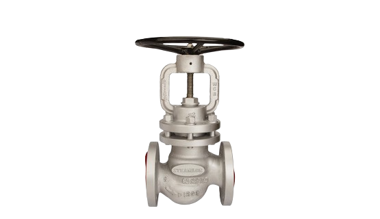
Piston Valves-slpv35
Image 1

Description


Piston valve is used to control the flow of fluid through pipes. Opening & closing of piston valves works on linear & rotary motion of piston within the body. Piston valves are seatless & glandless in design therefore they have some advantage over gate valves & globe valves. In piston valve seal rings are most important component for tight shut off. Piston vales are design with Class VI leak standard.

  • Unique sealing arrangement for extended life of valve
  • Wear & Erosion resistance for most of the fluids
  • Class VI leakage valve Standard
  • Use of Belleville washer to compensate thermal expansion
SIZE(NB) PMA TMA END CONNECTION
15, 20, 25, 40, 50, 65, 80, 100, 125, 150, 200 19.6 bar(g)
5.5 bar(g)
51.1 bar(g)
28.8 bar(g)
-29 to 38°C
425°C
-29 to 38°C
425°C
ASA 150
ASA 300